
Division
Relining
No-dig technologies
Renewing pipelines from within or along the existing route: no-dig technologies concentrate excavation at access points. The choice depends on network condition, materials, the fluid conveyed and site conditions.
Choose one of the six technologies to see how it works and explore our projects
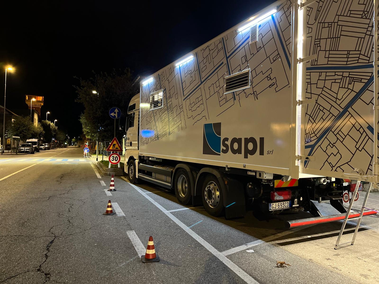
CIPP - Cured In Place Pipe
The technology
CIPP stands for Cured In Place Pipe: a lining formed and cured directly inside the pipe. A flexible sleeve, known as a liner, is impregnated with resin and inserted into the pipe to be rehabilitated.
The method allows work along the existing route through localised access points, limiting excavation and surface work.
SAPI EXPERIENCE
75,000 m
of sewer pipes rehabilitated with inversion CIPP
How it works
From diagnosis to final checks.
Assess the pipe
CCTV inspection records the internal condition of the network. Geometry, defects and access points provide the starting information for assessing rehabilitation options.
Learn more about CCTV inspections ↗Prepare the route
Cleaning and deposit removal prepare the pipe. Pipe condition and flow management are considered before installation.
Learn more about sewer and drain cleaning ↗The liner takes shape
A flexible, resin-impregnated liner advances through the pipe by inversion, using air or water pressure. This is the installation stage, separate from the subsequent curing process.
Complete the rehabilitation
The resin is cured using the chosen system. The liner becomes a rigid lining; the specified checks and inspections then follow.
The right approach for every network
The choice of lining and curing method depends on the pipe’s characteristics and the project requirements.
UV-CIPP
The technology
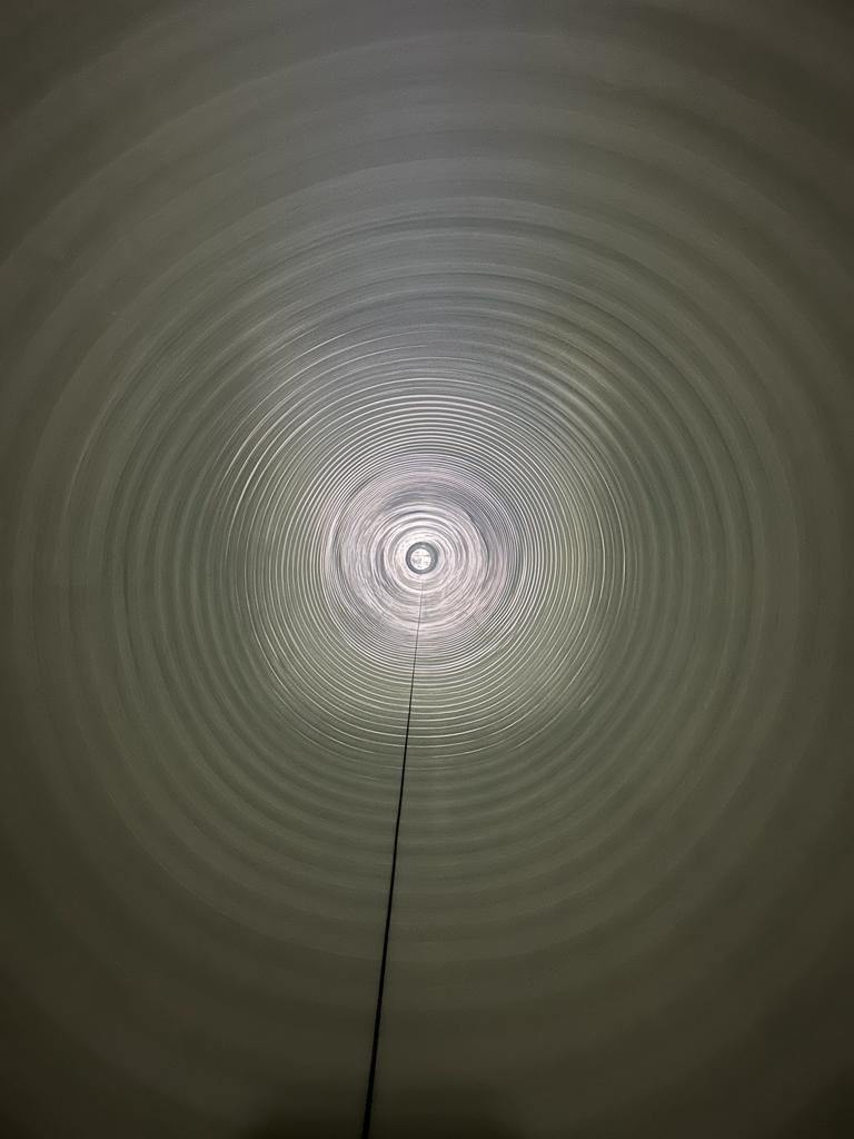
A liner, a resin-impregnated lining, is inserted into the pipe and cured with ultraviolet light. This forms a new structure inside the existing pipe.
UV light activates the liner’s resin inside the pipe. The material, installation method and curing parameters are defined for each project.
SAPI EXPERIENCE
5,600 m
of sewer pipes rehabilitated with UV-CIPP
How it works
From diagnosis to final checks.
Assess the pipe
CCTV inspection records the internal condition of the network. Geometry, defects and access points provide the starting information for assessing rehabilitation options.
Learn more about CCTV inspections ↗Prepare the route
Cleaning and deposit removal prepare the pipe. Pipe condition and flow management are considered before installation.
Learn more about sewer and drain cleaning ↗The liner takes shape
A flexible, resin-impregnated liner advances through the pipe by inversion, using air or water pressure. This is the installation stage, separate from the subsequent curing process.
Complete the rehabilitation
The resin is cured using the chosen system. The liner becomes a rigid lining; the specified checks and inspections then follow.
The right approach for every network
The choice of lining and curing method depends on the pipe’s characteristics and the project requirements.
Hose Lining
The technology
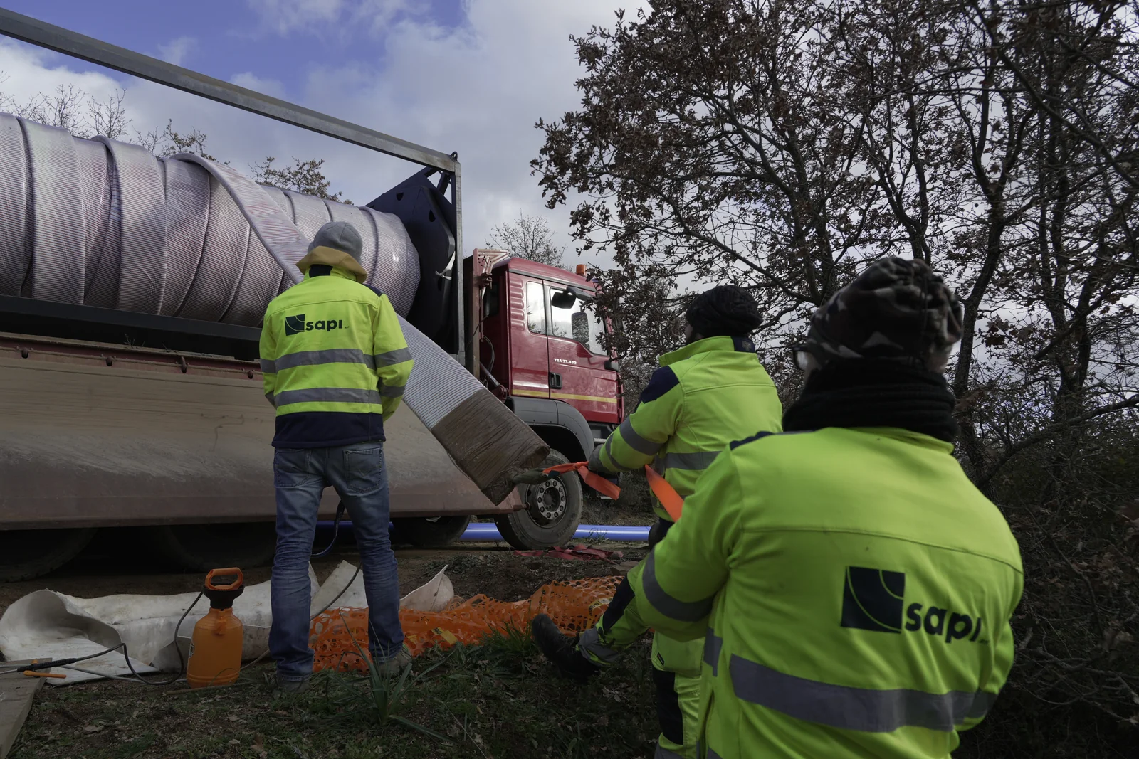
A flexible liner is inserted into the pipe to renew its fluid conveyance system. The existing network provides the route for the new element.
The flexible liner is pulled into the prepared network and connected at both ends with dedicated fittings. The system is selected according to the fluid, operating pressure and route.
SAPI EXPERIENCE
13,840 m
of pressurised water pipes rehabilitated with Hose Lining
How it works
From diagnosis to final checks.
Assess the network
The pipe’s route, geometry and internal condition help define the path of the flexible liner and the access points. The assessment also considers the fluid and operating pressure.
Learn more about CCTV inspections ↗Prepare the route
Access points are prepared and the host pipe is cleaned. The pulling system and flexible liner are arranged to suit the section to be rehabilitated.
Learn more about sewer and drain cleaning ↗Pull in the flexible liner
The flexible liner is pulled into the prepared pipe. Where required by the system, air is used to restore its circular shape before connections are made.
Reconnect the section
End fittings connect the flexible liner to the network. Leak tests and the checks specified in the design are completed before the section is returned to service.
The right approach for every network
The choice of lining and curing method depends on the pipe’s characteristics and the project requirements.
Pipe Bursting
The technology
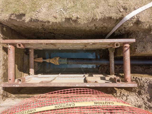
The existing pipe is broken in a controlled manner while a new pipe is installed along its route. Work proceeds from localised access points.
An expansion head breaks the existing pipe and pulls in the new one. Suitability requires an assessment of the pipe material, ground conditions and nearby networks.
SAPI EXPERIENCE
1,400 m
of pipes renewed with Pipe Bursting
How it works
From diagnosis to final checks.
Assess the route
The material and condition of the pipe to be replaced, ground conditions and potential conflicts with other underground utilities are assessed. These factors determine whether the technique is suitable.
Learn more about CCTV inspections ↗Prepare access points
The launch and reception points, pulling system and new pipe are prepared. Working areas are planned around the network and site conditions.
Learn more about sewer and drain cleaning ↗Burst and replace
The expansion head advances, breaking the existing pipe and displacing its fragments into the surrounding ground. At the same time, it pulls the new pipe along the route.
Complete the new pipeline
The new pipe is connected to the network. Fittings, connections and the checks specified in the design are completed before the pipe is returned to service.
The right approach for every network
The choice of lining and curing method depends on the pipe’s characteristics and the project requirements.
Slip Lining
The technology
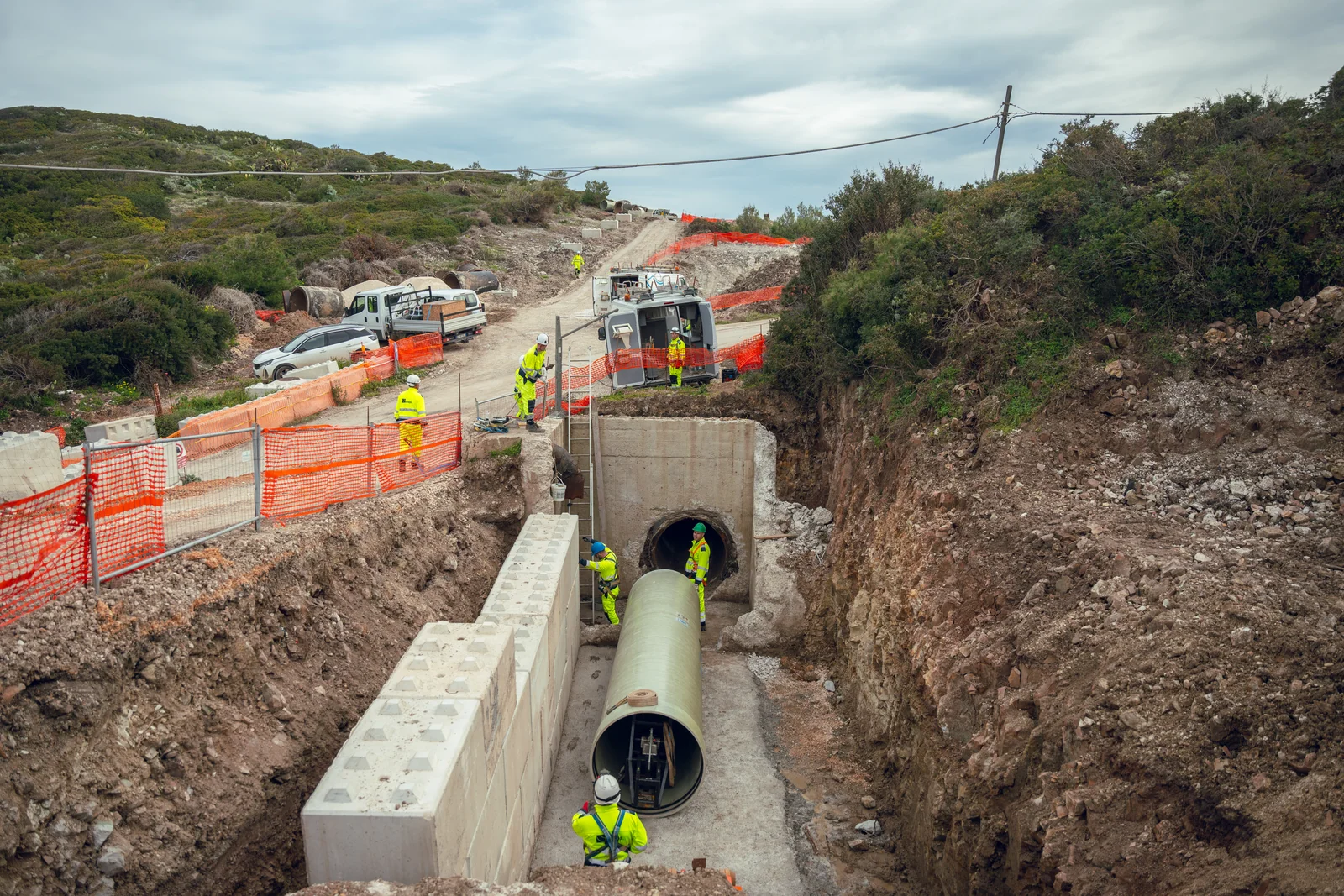
A new pipe is inserted inside the existing one. Using the existing route limits surface excavation work.
The new pipe has a smaller cross-section and is installed inside the host pipe. The design specifies its dimensions, connections and any required filling of the gap between the two pipes.
SAPI EXPERIENCE
2,200 m
of pressurised water pipes rehabilitated with Slip Lining
How it works
From diagnosis to final checks.
Check the available cross-section
The network’s geometry, internal condition and hydraulic requirements determine the pipe to be inserted. Its diameter must fit the available space inside the host pipe.
Learn more about CCTV inspections ↗Plan the installation
The existing pipe is cleaned and prepared, access points are arranged and the new pipe is assembled according to the installation design.
Learn more about sewer and drain cleaning ↗Install the new pipe
The new pipe is inserted into the host pipe, which remains around it. The smaller diameter leaves a gap between the two pipes, to be addressed as specified in the design.
Complete the renewal
Connections to the network are made and the annular gap is filled where specified in the design. Final checks complete the work before the pipe is returned to service.
The right approach for every network
The choice of lining and curing method depends on the pipe’s characteristics and the project requirements.
AMEX
The technology
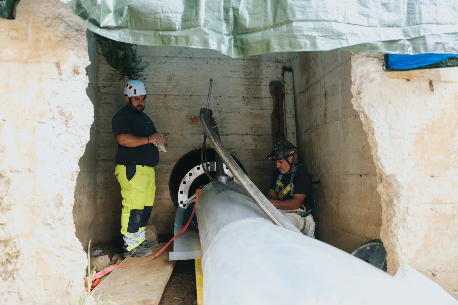
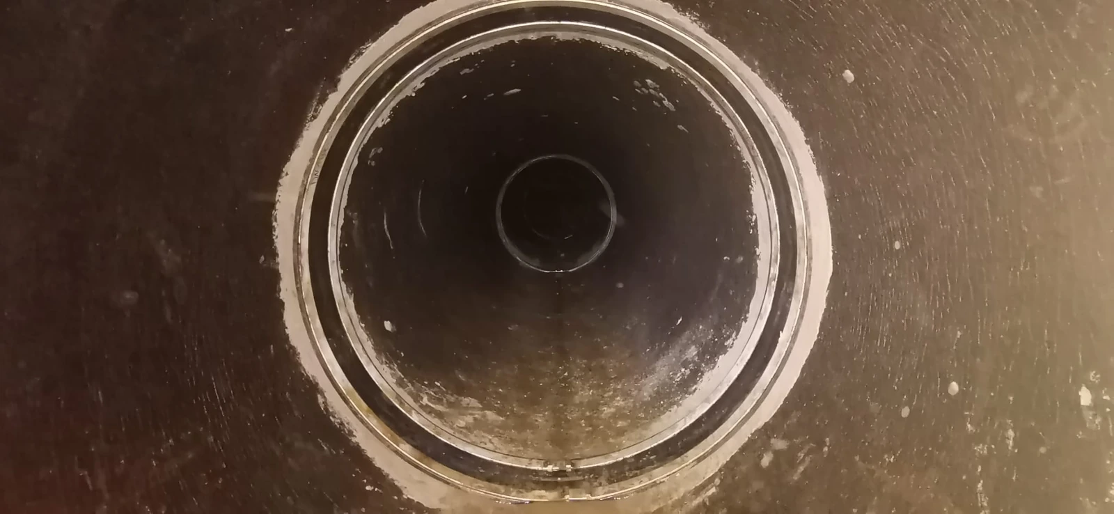
AMEX is an internal sealing system for pipe joints and localised defects. The repair focuses on the affected area, reached through suitable pipeline access points.
An elastomeric seal is pressed against the inner pipe wall by stainless steel bands. The bands are expanded with a hydraulic tool and mechanically locked to maintain sealing compression.
SAPI EXPERIENCE
900 seals
installed for localised pipe rehabilitation
How it works
The stages of the work. The photographs show joints already in place.
Locate the area to be repaired
The joint or localised defect, pipe geometry and condition are assessed. Access and the suitability of the sealing surface are checked.
Prepare the sealing surface
The affected area is cleaned and deposits are removed. Surface irregularities are corrected where necessary to allow the seal to make contact with the pipe wall.
Position and secure the seal
The seal is centred over the repair area. The stainless steel bands are expanded using hydraulic equipment and mechanically locked against the inner pipe wall.
Check the seal
Positioning and tightening are checked. Where specified, a leak test completes the checks before the pipeline returns to service.
The right approach for every network
The choice of lining and curing method depends on the pipe’s characteristics and the project requirements.